SAE AS 4877F pdf download – Bolts and Screws, Nickel Alloy UNS N0771 8, Classification: 1 85 ksi/1 200 °F Procurement Specification
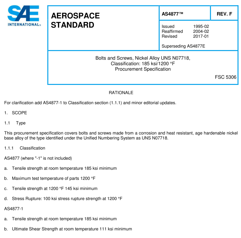
SAE AS 4877F pdf download – Bolts and Screws, Nickel Alloy UNS N0771 8, Classification: 1 85 ksi/1 200 °F Procurement Specification
1.2Application
Primarily for use in aerospace propulsion systems as follows:
a. For use up to approximately 1200 °F where elevated temperature tensile strength, stress-rupture strength, andresistance to relaxation are required.
b. For use up to approximately 800 °F where fatigue resistance and tensile strength are required.1.3Safety-Hazardous Materials
While the materials,methods, applications, and processes described or referenced in this specification may involve theuse of hazardous materials, this specification does not address the hazards which may be involved in such use. lt is thesole responsibiity of the user to ensure familiarity with the safe and proper use of any hazardous materials and to takenecessary precautionary measures to ensure the health and safety of all personnel involved.
2. REFERENCES
2.1 Applicable Documents
The following publications form a part of this document to the extent specified herein. The latest issue of SAE publicationsshall apply. The applicable issue of other publications shall be the issue in effect on the date of the purchase order. In theevent of conflict between the text of this document and references cited herein, the text of this document takesprecedence.Nothing in this document, however, supersedes applicable laws and regulations unless a specific exemptionhas been obtained.
2.1.1 SAE Publications
Available from SAE International, 400 Commonwealth Drive,Warrendale,PA 15096-0001,Tel: 877-606-7323 (inside USAand Canada) or +1 724-776-4970(outside USA), www.sae.org.
AMS2750
Pyrometry
AMS5662
Nickel Alloy, Corrosion and Heat-Resistant, Bars,Forgings, and Rings 52.5Ni – 19Cr – 3.0Mo – 5.1Cb (Nb)- 0.9OTi – 0.50Al – 18Fe Consumable Electrode or Vacuum Induction Melted 1775 °F (968 C) SolutionHeat Treated, Precipitation-Hardenable
AS1132
Bolts, Screws and Nuts – External Wrenching UNJ Thread, Inch – Design Standard
AS3062
Bolts, Screws and Studs, Screw Thread Requirements
AS3063
Bolts, Screws, and Studs, Geometric Control Requirements
AS8879
Screw Threads – UNJ Profile, Inch Controlled Radius Root with Increased Minor Diameter
2.1.2ASME Publications
Available from ASME, P.O.Box 2900,22 Law Drive,Fairfield,NJ 07007-2900, Tel:800-843-2763 (U.S./Canada),001-800-843-2763(Mexico),973-882-1170(outside North America), www.asme.org.
ASME B46.1 Surface Texture (Surface Roughness, Waviness,and Lay)
2.3 Unit Symbols
°C degree Celsius
°F degree Fahrenheit
cm 3 cubic centimeter
g gram, mass
% percent (1 % = 1 /1 00)
lbf pounds force
ksi kip (1 000 pounds) per square inch
sp gr specific gravity
3. TECHNICAL REQUIREMENTS
3.1 Material
Shall be AMS5662 heading stock.
3.2 Design
Finished (completely manufactured) parts shall conform to the following requirements:
3.2.1 Dimensions
The dimensions of finished parts, after all processing, including plating, shall conform to the part drawing. Dimensions shall apply after plating but before coating with dry film lubricants.
3.2.2 Surface Texture
Surface texture of finished parts, prior to plating or coating, shall conform to the requirements as specified on the part drawing, determined in accordance with ASME B46.1 .
3.2.3 Threads
Screw thread UNJ profile and dimensions shall be in accordance with AS8879, unless otherwise specified on the part drawing.
3.2.3.1 Incomplete Lead and Runout Threads
Incomplete threads are permissible at the entering end and the juncture of the unthreaded portion of the shank or adjacent to the head as specified in AS3062.
3.2.3.2 Chamfer
The entering end of the thread shall be chamfered as specified on the part drawing.
3.2.4 Geometric Tolerances
Part features shall be within the geometric tolerances specified on the part drawing and, where applicable, controlled in accordance with AS3063.
3.3 Fabrication 3.3.1 Blanks Heads shall be formed by hot forging or cold forging; temperature for hot forging blanks shall be within the range of 1 650 to 2000 °F. Machined heads are not permitted, except lightening holes may be produced by any suitable method. Wrenching recesses may be forged or machined. Flash or chip clearance in machined recesses shall not cause recess dimensions to exceed the specified limits.
3.3.2 Heat Treatment Headed blanks, before finishing the shank and the bearing surface of the head, cold rolling the head-to-shank fillet radius, and rolling the threads, shall be solution and precipitation heat treated as follows:
3.3.2.1 Heating Equipment Furnaces may be any type ensuring uniform temperature throughout the parts being heated and shall be equipped with, and operated by, automatic temperature controllers and data recorders conforming to AMS2750. The heating medium or atmosphere shall cause no surface hardening by carburizing or nitriding. The heat treatment atmosphere or medium shall not cause any surface contamination except as permitted by 3.3.3. On unplated bolts, discoloration from heat treatment is acceptable but no scale is permissible.
3.3.2.2 Solution Heat Treatment Headed blanks shall be solution heat treated by heating to a temperature within the range 1 725 to 1 850 °F, holding at the selected temperature within ±25 °F for 1 hour ± 0.1 hour, and quenching in oil, water, or an inert gas.
3.3.2.3 Precipitation Heat Treatment After solution heat treatment as in 3.3.2.2, headed blanks shall be precipitation heat treated by heating to 1 325 °F ± 1 5 °F in a controlled atmosphere, holding at heat for 8 hours ± 0.25 hour, furnace cooling at 1 00 °F ± 1 5 °F per hour to 1 1 50 °F ± 1 5 °F, holding at 1 1 50 °F ± 1 5 °F for 8 hours ± 0.25 hour and cooling at a rate equivalent to air cool. Instead of the 1 00 °F per hour cooling rate to 1 1 50 °F ± 1 5 °F, parts may be furnace cooled at any rate provided the time at 1 1 50 °F ± 1 5 °F is adjusted to give a total precipitation heat treatment time of approximately 1 8 hours.
