ASME A112.1.2 pdf download
ASME A112.1.2 pdf download Air Gaps in Plumbing Systems (For Plumbing Fixtures and Water-Connected Receptors) 1GENERAL1.1 Scope This Standard identifies methods of providing protec-tion against backsiphonage through means of an air gapand establishes physical requirements and methods oftesting air gaps for plumbing fixtures and waterreceptors. 1.2 Units of Measurement The values stated in either SI (Metric) or inch/poundunits are to...
ASME A112.3.1 pdf download
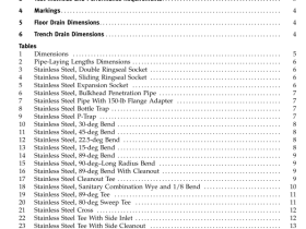
ASME A112.3.1 pdf download Stainless Steel Drainage Systems for Sanitary DWV, Storm, and Vacuum Applications, Above- and Below-Ground 2 REQUIREMENTS 2.1 Dimensions All dimensions for stainless steel pipe, fittings, drains, and adapters are found in Tables 1 through 47. All threaded inch values shall comply to ASME B1.20.1. Threaded dimensions shall be identified as either “inch dimensions” according to ASME...
ASME A112.3.4 pdf download
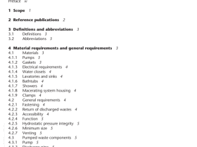
ASME A112.3.4 pdf download Plumbing fixtures with pumped waste and macerating toilet systems 1 Scope 1.1 This Standard establishes physical, performance, and testing requirements applicable to plumbing fixtureswith pumped waste, macerating toilet systems, and related components. Such systems are intended tocollect waste from a single fixture such as a water closet, lavatory, shower, or bathtub and pump thesewastes to some...
ASME A112.4.2 pdf download
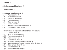
ASME A112.4.2 pdf download Personal hygiene devices for water closets 1 Scope 1.1 This Standard covers personal hygiene devices for water closets and specifies requirements for materials,construction, performance, testing, and markings. 1.2 Products covered by this Standard include bidet sprayers and other retrofit personal hygiene devicesintended (a)for water closets and water closet seats; and (b)to be used with hot and...
ASME A112.6.7 pdf download
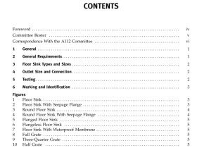
ASME A112.6.7 pdf download Sanitary Floor Sinks 2.2.1 Surface Epoxy. The surface epoxy, visible after installation, shall be glossy to the extent that it will have a 60 deg (1.05 rad) specular gloss of not less than 60 when tested in accordance with para. 5.2. 2.2.2 Epoxy Thickness. The thickness of the epoxy coating, as measured on a flat surface...
ASME A112.14.3 pdf download
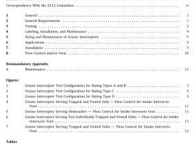
ASME A112.14.3 pdf download Hydromechanical Grease Interceptors 2.2 Inlet and Outlet Connections 2.2.1 The inlet and outlet connections of the grease interceptor shall be either pipe thread or of a plain end diameter to allow hubless coupling connections. The manufacturer’s installation requirements shall iden- tify installation parameters sufficiently to enable connec- tion consistent with the test parameters ofthis Standard. 2.2.2...
ASME A112.14.4 pdf download
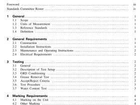
ASME A112.14.4 pdf download GREASE REMOVAL DEVICES 2.3 Maintenance and Operating Instructions Each GRD shall be provided with service instructions, which include a trouble shooting guide as well as instructions for performing necessary servicing or ob- taining outside servicing. Units shall be provided with complete maintenance and operating instructions. 2.4 Electrical Requirements All electrical components used in the GRD shall...
ASME A112.14 pdf download
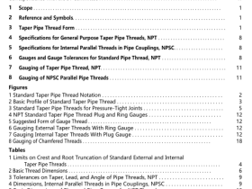
ASME A112.14 pdf download Pipe Threads, 60 deg, General Purpose 4SPECIFICATIONS FOR GENERAL PURPOSE TAPERPIPE THREADS,NPT 4.1 Taper Pipe Threads, NPT NPT threads made in accordance with these specifica-tions consist of an external taper and an internal taperthread, to form the normal type of joint having generalapplication on pipe and fittings. See Fig. 3. NPT taper pipe threads are intended...
ASME A112.14.6 pdf download
ASME A112.14.6 pdf download FOG (Fats, Oils, and Greases) Disposal Systems 3 SPECIAL REQUIREMENTS 3.1 Separation/Retention Efficiency FOG disposal systems shall have a minimum separa- tion/retention efficiency in accordance with ASME A112.14.3 or PDI-G101. 3.2 Application Documentation Each FOG disposal system shall be provided with complete applicationinstructions including, butnotlim- ited to, the following: (a) flow control and/or vent requirements (b)...
ASME A112.18.1 pdf download
ASME A112.18.1 pdf download Plumbing supply fittings Note: Coating surface deformations that appear after performance testing (e.g., stretch marks, flow lines under thecoating, or deformations caused by stress relieving of the substrate) and do not separate, peel, or come loose are notconsidered cracks. Pit – a small depression or cavity. Surface defect — a pit, blister, crack, peeling, wrinkling, corrosion,...